NWHD Series
Pneumatic Zero Loss Drain
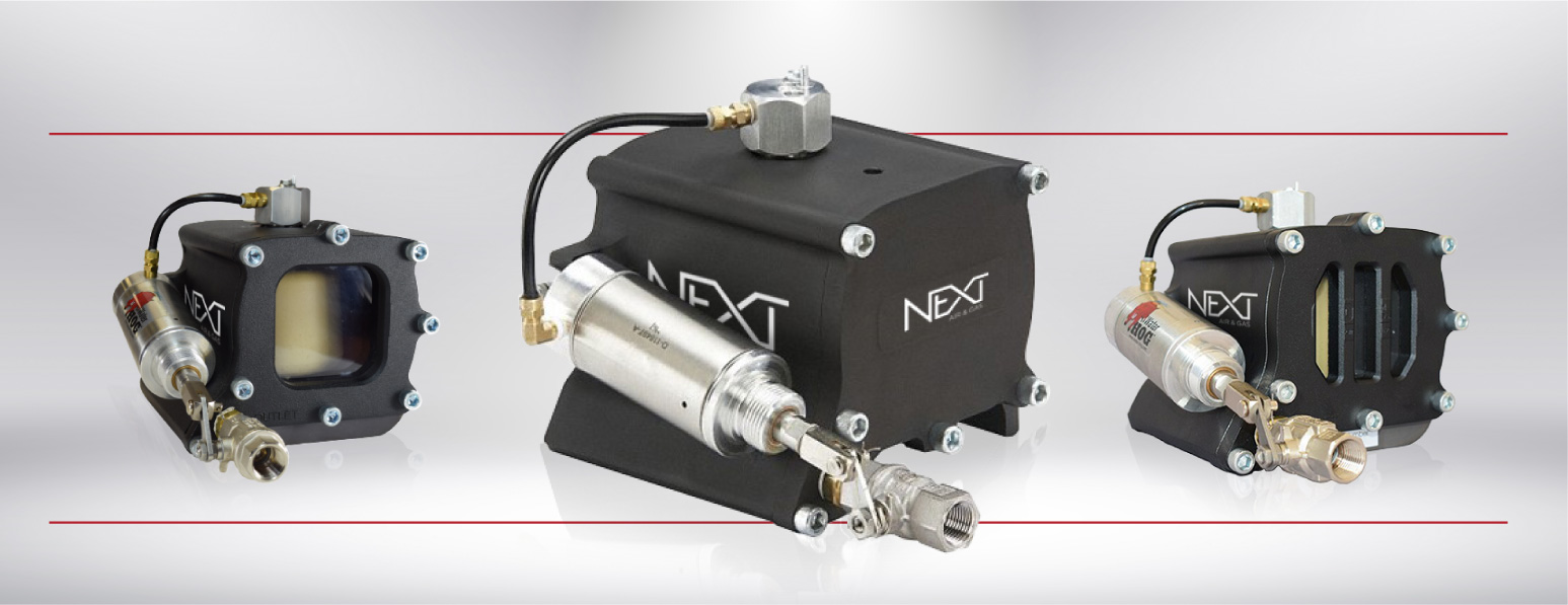
The AQUA-PURE- NWHD is a state-of-the-art, low-profile, pneumatically powered zero-loss drain trap ideal for compressed air systems up to 100 HP. Its unique design avoids small passages thus ensuring clog-free operation. The NWHD is fully automatic, operating with no timer or manual settings, it’s powered by compressed air. No need for electrical connections. The sleek, low-profile design allows this product to fit where others may not be able to.
NWHD Series Features
Powers Through Condensate Build Up
- Ideal for compressor applications up to 100 hp; The NWHD design avoids small passages ensuring clog-free operation.
Fully Automatic Operation
- No Timer or Manual Settings
No Electrical Connections
- The NWHD is fully pneumatically operated, avoiding the need for electrical wiring and connections.
Energy Saving Operation
- Zero Compressed Air Loss. Check with your utility to see if the NWHD qualifies for energy efficiency incentives. The NWHD pays for itself when replacing open condensate drain valves or timer traps.
Low Profile Design
- The 4.7” vertical operating height allows the NWHD to fit where other larger units can’t.
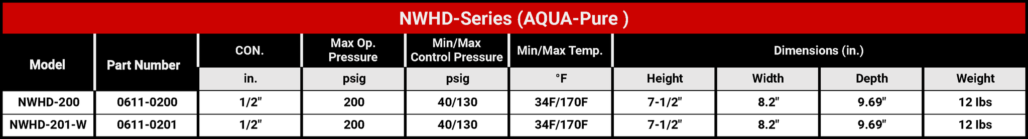
Connections
- ½” in (npt)
Drain Inlet / Outlet Diameter
- ½ in (npt)
Min Pressure
- 40 (psig)
- 2.7 (barg)
Max Pressure
- 200 (psig)
- 13.7 (barg)
Min-Max Control Pressure
- 40 to 130 (psig)
- 2.7 to 8.9 (barg)
Operating Temp Range
- 33° to 170° F
- .5 to 77° C
Drain Rate @100 psig / 6.8 barg
- 0.9 (gpm)
Bowl Capacity
- 1.25 (pt)
Cycle time
- 10 seconds
Max Liquid Temperature
- 170° F
- 77° C
Capacity
- Varies with pressure / piping
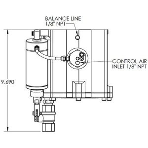
Overall Height
- 7-1/2” in
Overall Width
- 8.2” in
Overall Depth
- 9.69” in
Weight
- 12 lbs
Body Material
- Aluminum
Housing & Front Plate
- Anodized Aluminum
Control circuit and Air Cylinder
- Aluminum
Float
- Polyurethane
Hosing Seal and O Rings
- Fluorocarbon
Fittings
- Brass
Ball Valve
- Nickel Plated Brass
Front Plate Hardware Clevis
- Zinc Plated Steel
Control Leber and Shouldered Bold
- Stainless Steel
NWHD Series
Top View
Front View
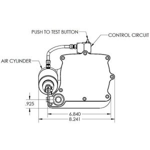
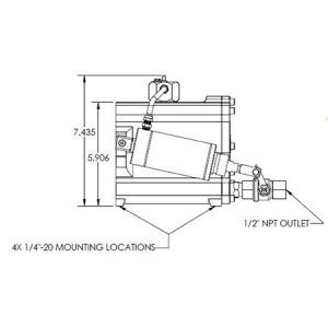
Side View
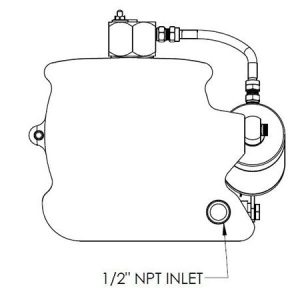
Back View
NWHD Series Options

Your next step toward working with NEXT Air & Gas is to contact us for a Quote. Fill out the information below and give us the appropriate information needed to get started. Be sure to fill out all the contact information and our team will reach out with any questions or concerns.
If you’d rather speak to Sales Engineering, feel free to contact us at (865) 635-8178.
Below are links to product information and brochures. Please click and download at your convenience. If you have any questions or suggestions on materials you think would be helpful, please call us at (865) 635-8178.
Principles of Operation
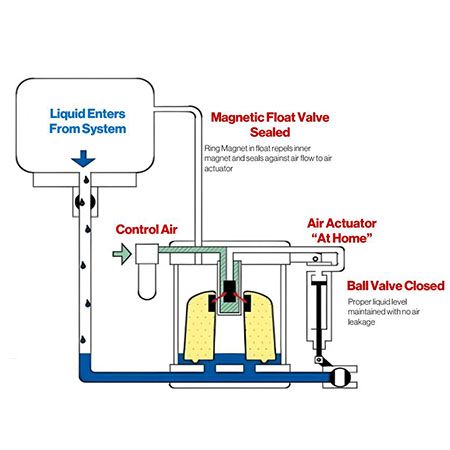
Start Cycle
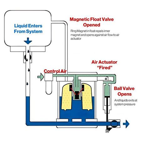
The Polymer Float with integral magnet is resting on the base of the reservoir. The integral float magnet exerts a magnetic force repelling in the inner magnet upward and holding it seated against an orifice in the lower end of the control air valve stem. The control air circuit, including the inner magnet and valve stem, is isolated from liquid that flows into the reservoir. The air actuator is in the home position in the discharge ball valve is closed (Figure: 1)
Start of Discharge
Liquid continues to flow into the reservoir and raises the float to its highest position. The integral float magnet is then raised up past the inner magnet and repels the inner magnet downward opening the orifice in the control air valve stem. This allows the control air from the center tube to flow through the other side of the control air circuit to the actuator. Control air pressure extends the air actuator and opens the ball valve starting the discharge of the liquid accumulated in the reservoir. (Figure: 2)
Frequently Asked Questions
Where Should A NWH Drain Be Installed?
At Liquid Accumulation Points Within a System at Compressors, Air Receiver Tanks, Intercoolers, Aftercoolers, Dryers, Separators, Filters and Drip Legs.
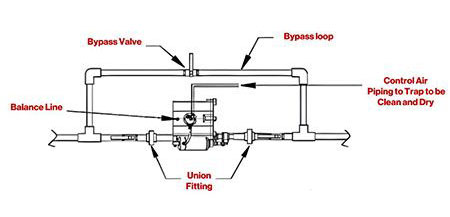
Is It Mandatory To Use a Balance Line?
Yes. The Balance Line Provides a Means to Handle the Displaced Air From the Reservoir as the Liquid Enters the Reservoir.
What Size Compressor Can it Handle?
The NWH Drain Will Function Effectively on Any Size Compressor, Compressed Air System, Up to 100hp.
Can the NWH Drain Be Used to Drain Multiple Tanks and / or Compressor Systems?
No. They Will Not All be of Precisely the Same Pressure Level and the Liquid Would Accumulate in the Lowest Pressure Drain or System Thereby Bypassing the WaterHog™. Also, the Use of Check Valves in Multiple Drains to One WaterHog™ Installation Will Not Make This Work Properly. Always Install One WaterHog™ for Each Item of Equipment to be Drained.
Can the Balance Line and the Control Air Line be Hooked Together via a Tee Connection?
No. Do Not Do This. Each of These Air Lines Has Its Own Specific Purpose and Should Never be Tied Together. The Control Air Should be the Cleanest Driest Air Available Since it Supplies Air to the Control Circuit to Operate the Pneumatic Actuating Cylinder Which Functions Best and Lasts Longer if Clean Dry Air is Used. The Balance Line Allows the Air in the Reservoir to Move Out Leaving Room in the Reservoir for the Incoming Liquid. This Air Contains Moisture that Would be Drawn Across a Tee Fitting Tied to the Control Air Line and be Pulled Directly Into the Control Air Circuit, Which Can Damage Control Air Pathways and the Air Cylinder.
Methods of Installation
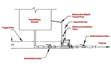
Method 1
Use this piping layout drawing in the case where the bottom of the vessel being drained is above the trigger point of the trap but not high enough to connect the balance line to the vertical section of the drain line.
Connect the balance line to the vessel being drained such that the pressure of the liquid entering the trap is the same as the pressure of the balance line. The balance line must be sloped from the connection point of the vertical drain line downward toward the trap.
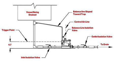
Method 2
Use this piping layout drawing in the case where the bottom of the vessel being drained is above the top of the trap enough that the balance line can be connected to the vertical section of the drain line as shown. The balance line must be sloped from the connection point of the vertical drain line downward toward the trap.
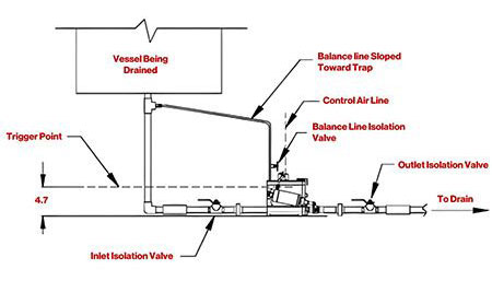
Method 3
Use this piping layout drawing in the case where the bottom of the vessel being drained is below the trigger point of the trap (4.7 inches above the floor). In this Case, the balance line must be vented to atmosphere to prevent liquid from accumulating inside the vessel being drained. See the product installation guide for the procedure on adjusting the amount of venting properly.
Typical Bypass Circuit